What is the role of vibrating screen in wastewater treatment

A vibrating screen plays a crucial role in wastewater treatment, primarily in the pre-treatment stage to remove solid materials from the incoming wastewater stream.

Vibrating screen in wastewater treatment role

Single layer horizontal sieve

1. Removal of Large Solids and Debris:

Vibrating screens act as a physical barrier with specific mesh sizes. As wastewater flows over the vibrating screen, larger solids like rags, plastics, paper, wood, and grit are retained on the screen surface.

The vibrations help to agitate the wastewater, encouraging smaller particles and water to pass through the screen openings while preventing the screen from clogging.

2. Protection of Downstream Equipment:

By removing large and abrasive solids early in the treatment process, vibrating screens prevent damage, blockages, and excessive wear on pumps, pipes, valves, and other sensitive equipment in subsequent treatment stages. This reduces maintenance costs and downtime.

3. Improved Efficiency of Subsequent Processes:

The removal of gross solids reduces the organic and inorganic load on downstream treatment units like sedimentation tanks, biological reactors, and filters. This enhances their efficiency and overall performance.

For example, removing grit and sand prevents their accumulation in sedimentation tanks, maintaining the tank’s effective volume and reducing the frequency of sludge removal.

Double banana sieve

4. Sludge Dewatering:

Vibrating screens can also be used in sludge dewatering processes to separate excess water from the treated sludge, reducing its volume and making it easier and more cost-effective to handle and dispose of.

Types of Vibrating Screens Used in Wastewater Treatment:

High Frequency Dehydration Vibrating Screen

Various types of vibrating screens are employed based on the specific requirements of the wastewater treatment plant, including:

Inclined Vibrating Screens: These are mounted at an angle, using gravity to aid material flow.

Horizontal Vibrating Screens: Suitable for high throughput and larger particles.

Multi-Deck Screens: Feature multiple screening layers for simultaneous separation of different particle sizes.

Linear Vibrating Screens: Utilize linear motion for efficient material conveyance.

Circular Vibrating Screens: Employ circular or elliptical motion, often for higher throughput applications.

In summary, the vibrating screen is a vital piece of equipment in wastewater treatment, ensuring the efficient removal of solid pollutants in the initial stages, protecting downstream processes, and contributing to the overall effectiveness of the treatment plant.

How to Separate Sticky Materials by Vibrating Screen

Separating sticky materials poses a significant challenge in screening operations, especially in industries like mining, recycling, and agriculture. Traditional vibrating screens often struggle to handle sticky, moist, or cohesive materials due to screen blinding, material buildup, and reduced screening efficiency.

However, with proper screen design, vibration techniques, and surface treatments, vibrating screens can effectively separate even the most difficult-to-process materials. Understanding the right methods and equipment configurations is key to optimizing performance and minimizing downtime when dealing with sticky substances.

How to Separate Sticky Materials by Vibrating Screen

Cooperation Customer

Effectively separating sticky materials requires modifications to the screen, the process, or sometimes the material itself. Here’s how to approach it:

1. Screen Media Selection & Configuration:

Self-Cleaning Screen Media: This is often the most effective solution.

Polyurethane or Rubber Screens: These materials are flexible. The inherent vibration causes the flexible strands or apertures to constantly move, flexing and contracting, which helps dislodge sticky particles and prevent blinding. They come in various aperture shapes (square, slotted, round).

Wire Mesh with Flexible Elements: Some wire mesh designs incorporate polyurethane strips or other flexible components to achieve a similar self-cleaning effect.

Piano Wire / Harp Screens: Composed of individual longitudinal wires that can vibrate independently at high frequencies. This vigorous, independent movement is very effective at preventing blinding with near-size particles and slightly sticky material. Less robust than polyurethane.

Larger Aperture (If Possible): Using a slightly larger aperture than theoretically required can sometimes reduce blinding, but this depends on the acceptable product specification.

Slotted Apertures: Long, narrow openings can sometimes handle sticky materials better than square openings, especially if the particle shape allows passage. Orient slots parallel to the material flow.

2. Anti-Blinding Devices:

These are retrofitted or built-in systems designed to actively clear the mesh:

Ball Trays / Ball Decks: A perforated plate is installed below the screen mesh, creating compartments containing rubber or polyurethane balls. As the screen vibrates, the balls bounce aggressively against the underside of the screen mesh, dislodging stuck particles. Very common and effective for moderate stickiness.

Slider Decks / Ring Decks: Similar in concept to ball trays, but use plastic rings or sliders that move back and forth beneath the mesh, scraping or knocking particles loose. Can be effective for materials that might trap or damage balls.

Ultrasonic Deblinding Systems: High-frequency, low-amplitude vibrations are transmitted directly to the screen mesh via transducers and resonators. This micro-vibration is extremely effective at preventing blinding with very fine powders and moderately sticky materials by breaking the surface tension and static bonds holding particles to the mesh. More expensive but highly effective for specific applications.

High Frequency Dehydration Vibrating Screen

3. Adjusting Vibration Parameters:

Increase G-Force / Amplitude: A more aggressive vibration (higher stroke/amplitude) can impart more energy to the particles, helping to break agglomerates and throw material off the mesh surface, reducing sticking and blinding. Be cautious, as excessive force can damage the screen or degrade fragile materials.

Optimize Frequency: While higher amplitude is common, adjusting the frequency (speed) can sometimes help find a “sweet spot” for specific sticky materials.

Change Stroke Type/Angle:

Linear Stroke: Often better for conveying sticky materials across the deck.

Circular/Elliptical Stroke: Can be more effective at the feed end for stratification and breaking lumps, but may be less efficient at conveying sticky material downhill. Some screens offer variable stroke types. Adjusting the stroke angle (on inclined screens) can influence travel speed and bed depth.

4. Modifying Process Conditions:

Control Feed Rate: Avoid overloading the screen. A thinner, consistent bed depth allows particles better access to the screen openings and reduces the pressure that can force sticky particles into the mesh. Use a controlled feeder (vibratory, belt).

Improve Feed Distribution: Ensure material spreads evenly across the full width of the screen deck as it enters. Poor distribution leads to localized overloading and blinding.

Increase Screen Deck Angle: A steeper incline uses gravity more effectively to encourage material flow across the deck, reducing residence time and the chance for material to stick.

Use Water Spray / Wet Screening (If Applicable): If the process allows for wet material, adding controlled water spray bars above the screen deck can wash fines through, lubricate particles, and keep the mesh clear. This turns it into a washing/rinsing operation.

Heated Screen Decks: For materials whose stickiness is temperature-dependent (e.g., waxes, some plastics, materials sticky due to condensation), applying low-voltage electrical current to the screen mesh can generate gentle heat. This can reduce surface moisture or lower the viscosity of sticky binders, preventing blinding. Requires specialized equipment and safety considerations.

5. Material Pre-Treatment (If Possible):

Drying: If stickiness is primarily due to moisture, pre-drying the material can significantly improve screenability.

Cooling: Some materials are sticky only when warm; cooling them beforehand can help.

Adding Flow Aids: Small amounts of inert, fine powders (like fumed silica, talc, calcium carbonate – if contamination is acceptable) can coat the sticky particles, reducing their tendency to agglomerate and stick to surfaces.

Conditioning/Lump Breaking: If large, sticky lumps are present in the feed, pre-breaking them before they reach the screen can improve efficiency.

Arc Vibrating Screen

Key Considerations:

Testing: Due to the variability of sticky materials, lab testing or pilot-scale trials are highly recommended before investing in specific solutions.

Maintenance: Regular inspection and cleaning are crucial, even with anti-blinding systems. Build-up can still occur on side plates and other non-screening surfaces.

Cost vs. Effectiveness: Solutions range from simple adjustments to expensive specialized equipment (like ultrasonic systems or heated decks). Choose based on the severity of the problem and budget.

Consult Manufacturers: Screen manufacturers have extensive experience and can provide tailored recommendations based on your specific material and application.

By systematically addressing these points, you can significantly improve the performance of vibrating screens when handling challenging sticky materials. Often, a combination of strategies is required for optimal results.

Vibrating Screen Wear Protection Solutions

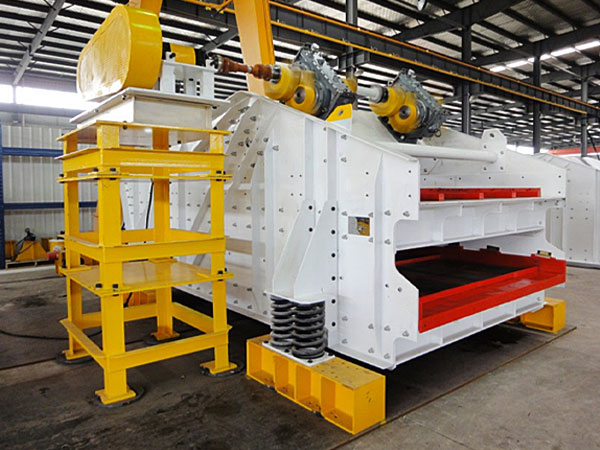
Vibrating screens are critical equipment in mining, aggregate, and industrial processing, but they are prone to wear due to constant vibration, material impact, and abrasion. Implementing effective wear protection solutions can significantly extend screen life, reduce downtime, and improve efficiency.

Vibrating Screen Wear Protection Solutions

Cooperation Customer

1. Screen Media Wear Protection: (The most critical wear surface)

Material Selection:

High-Carbon Steel Wire Mesh: Standard, cost-effective, good abrasion resistance for many applications. Different weaves (e.g., square, slotted) affect wear life and open area.

Stainless Steel Wire Mesh: Offers corrosion resistance in addition to abrasion resistance, suitable for wet or corrosive environments. More expensive than high-carbon.

Polyurethane (PU) Panels: Excellent abrasion resistance, especially in wet applications. Good impact resistance, noise reduction, and often longer life than wire mesh in abrasive conditions.

Modular panels allow replacing only worn sections. Can be prone to cutting by sharp materials.

Rubber Panels: Superior impact resistance, good for large, heavy feed material. Excellent noise damping. Good abrasion resistance, particularly in wet sliding abrasion scenarios. Can be less efficient (lower open area) than wire mesh. Modular options available.

Perforated Steel Plate: Very robust, used for heavy-duty scalping applications with large, impactful material. Lower open area compared to mesh. Can be made from abrasion-resistant (AR) steel.

Hybrid Screens: Combine different materials (e.g., PU frame with wire mesh inserts) to optimize open area and wear life in specific zones.

Profile Wire / Wedge Wire: Smooth surface reduces plugging and wear in some applications, often used for dewatering or specific fine screening.

Configuration:

Modular Systems (PU/Rubber): Allow targeted replacement of high-wear areas, reducing overall replacement cost and downtime compared to full-deck tensioned media.

Proper Tensioning (Wire Mesh): Crucial for wire mesh. Loose screens flap, causing premature fatigue failure and accelerated wear. Over-tensioning can also cause failure. Use manufacturer recommendations and check tension regularly.

Crowned Deck: Helps tension wire mesh properly and can aid material distribution.

Double banana sieve

2. Feed Box / Feed Chute Wear Protection: (High impact and initial abrasion)

Abrasion-Resistant (AR) Steel Liners: Hardened steel plates (e.g., AR400, AR500) bolted or welded in place. Good balance of impact and abrasion resistance, cost-effective.

Rubber Liners: Excellent for absorbing high impact from falling material. Reduces noise significantly. Best suited where impact is the primary concern over sliding abrasion.

Polyurethane (PU) Liners: Good combination of impact and sliding abrasion resistance, especially in wet conditions.

Ceramic Liners: Extremely high resistance to sliding abrasion, but can be brittle and susceptible to cracking under direct high impact. Often used in combination with rubber (rubber-backed ceramics) to improve impact resistance. Best for fine, highly abrasive material with lower impact.

Chromium Carbide Overlay (CCO) Plate: Very high abrasion resistance due to hard chromium carbide particles in a softer matrix. Good for severe sliding abrasion, moderate impact. Can be welded or bolted.

Dead Box / Rock Box Design: Designing the feed box so that a layer of the material being processed builds up and forms a natural wear liner, protecting the steel structure underneath. Material impacts material, drastically reducing wear on the liner itself.

Single layer horizontal sieve

3. Side Plate Wear Protection: (Sliding abrasion from material moving along the sides)

AR Steel Liners: Most common solution, bolted for easy replacement.

Rubber or PU Liners: Reduce noise and offer good wear life, especially if there’s some impact against the sides.

CCO Plate or Ceramic Liners: Used in highly abrasive applications.

4. Discharge Lips Wear Protection: (Sliding abrasion as material exits)

AR Steel Liners: Commonly used, often thicker or harder grade than side liners due to concentrated wear.

Replaceable Bolt-on Lips: Designing the lip as a separate, easily replaceable wear component made of AR steel, CCO, or PU.

Hardfacing: Applying a wear-resistant weld overlay directly to the discharge lip area (can be done during manufacturing or as a repair).

5. Screen Deck Structure / Cross Member Protection:

Rubber or PU Capping: Covering the tops of deck support bars (where screen media rests) protects them from abrasion from the underside of the screen media or migrating fines. This is essential for modular systems and highly recommended for tensioned media.

Profiled Cross Members: Some designs use specifically shaped cross members to minimize flat surfaces where material can build up and cause wear.

Linear Vibrating Screen

6. Operational and Maintenance Practices:

Proper Feed Distribution: Ensure material spreads evenly across the screen width. Concentrated flow drastically accelerates wear in specific areas. Adjust chute design or use distributors if needed.

Avoid Overloading: Running the screen beyond its capacity increases bed depth, reduces efficiency, and accelerates wear.

Control Feed Rate: Surges in feed can cause impact damage and overload.

Regular Inspections: Frequently check all wear areas (media, liners, structure) for wear patterns and damage.

Timely Replacement: Replace worn components before they fail catastrophically or cause damage to underlying structures.

Correct Component Installation: Ensure liners are bolted securely and screen media is installed/tensioned correctly. Loose components wear faster and can damage the screen structure.

Cleaning: Prevent material buildup, especially sticky or corrosive material, which can trap abrasive particles or cause corrosion.

Selecting the Right Solution:

The best solution depends on:

Material Characteristics: Size, shape, hardness, moisture content, corrosivity.

Application: Scalping, fine screening, wet/dry processing.

Impact Levels: Height of drop onto the screen.

Operating Conditions: Tonnage, temperature.

Budget: Initial cost vs. lifespan and replacement cost.

Maintenance Capabilities: Ease of inspection and replacement.

The best wear protection depends on the material being processed (e.g., abrasive ores vs. lightweight aggregates). Combining durable screen media, protective liners, reinforced components, and proper maintenance maximizes screen lifespan and operational efficiency.

How to adjust the vibration force of the vibrating screen

The vibration force of a vibrating screen is a critical factor that directly impacts screening efficiency, material flow rate, and overall equipment performance. Whether you’re dealing with fine powders or coarse aggregates, proper adjustment of vibration force ensures optimal separation and prevents excessive wear or mechanical failure. Understanding how to fine-tune the vibration settings can help you adapt to different materials, improve productivity, and extend the lifespan of your machine. In this guide, we’ll walk you through the basic principles and step-by-step methods for adjusting the vibration force of your vibrating screen effectively and safely.

Vibrating screen vibration force adjustment

Cooperation Customer

Adjusting the vibration force (often referred to as excitation force or G-force) of a vibrating screen is crucial for optimizing screening efficiency, preventing damage to the screen, and adapting to different material types or feed rates. The exact method depends heavily on the specific design of the screen’s vibrator mechanism, but here are the common ways it’s done:

1. Adjusting Eccentric Weights (Most Common Method):

Mechanism: Most vibrating screens use rotating shafts with eccentric counterweights. The rotation of these unbalanced weights generates the vibration. The amount of force generated depends on the mass of the weights and their distance from the center of rotation (eccentricity).

How to Adjust:

Adding/Removing Weight Plates: Many systems have counterweights composed of several stacked plates or blocks. By adding or removing these plates (usually in symmetrical pairs on both sides of the shaft or on corresponding shafts), you change the total rotating unbalanced mass, thus increasing or decreasing the vibration force.

Changing Weight Position (Angle/Radius): Some designs feature adjustable counterweights that can be rotated relative to the shaft or to each other.

Single Adjustable Weight: A single block might be designed to slide radially outwards (increasing force) or inwards (decreasing force) and then be locked in place.

Multiple Adjustable Weights: Often, there are two or more weight segments per side. By changing the angle between these segments, you change the effective eccentricity (the distance of the combined center of mass from the shaft center). Moving them closer together (aligned) maximizes the force; moving them further apart (opposed) minimizes or cancels out the force.

Location: These weights are typically located at the ends of the vibrator shaft(s), often enclosed within protective guards.

Procedure:

Safety First: ALWAYS lock out and tag out the power supply to the screen before removing guards or making adjustments.

Remove the protective guards covering the eccentric weights.

Loosen the bolts securing the weights.

Add/remove plates or adjust the angular position of the weights according to the manufacturer’s instructions. Crucially, adjustments must be identical on both sides of the screen (or on corresponding shafts) to maintain balanced vibration and prevent damage.

Ensure weights are securely tightened to the specified torque.

Reinstall the guards.

Test run the screen and observe performance.

2. Adjusting Speed (RPM):

Mechanism: Vibration force is proportional to the square of the rotational speed (RPM). Therefore, changing the speed significantly impacts the force.

How to Adjust:

Variable Frequency Drive (VFD / VSD): If the screen motor is controlled by a VFD, adjusting the frequency output directly changes the motor speed and thus the vibration force. This is the easiest and most flexible method if available.

Changing Pulleys (Sheaves): For belt-driven systems without a VFD, you can change the size ratio of the motor pulley and the vibrator shaft pulley. A smaller motor pulley or a larger vibrator pulley will decrease speed (and force); a larger motor pulley or a smaller vibrator pulley will increase speed (and force). This requires calculating the correct pulley sizes and potentially changing the belt length. This is a less common adjustment method used more for initial setup or major process changes.

Considerations: Changing speed also affects the vibration frequency, which can influence screening efficiency differently than just changing the force (amplitude/stroke). There’s usually an optimal speed range for a given screen design and application.

Linear Vibrating Screen

3. Adjusting Stroke Angle (Angle of Throw):

Mechanism: Primarily relevant for linear-motion screens driven by two counter-rotating shafts (geared exciters). The relative timing (phasing) of the weights on the two shafts determines the direction of the linear stroke.

How to Adjust: By changing the relative angular position of the gears connecting the two exciter shafts, the angle of throw can be adjusted. This doesn’t directly change the total force generated but alters its direction, affecting how material travels across the deck (e.g., faster conveying vs. more lifting action).

Note: This is distinct from adjusting the magnitude of the force by changing the weights themselves.

Important Considerations Before Adjusting:

Consult the Manufacturer’s Manual: This is the MOST IMPORTANT step. Every screen is different. The manual will provide specific instructions, diagrams, torque specifications, and safety procedures for your model.

Safety: Lockout/Tagout (LOTO) procedures are mandatory before working on the equipment. Rotating parts can cause severe injury.

Symmetry: Ensure any adjustments to weights are made identically on both sides of the screen to prevent uneven forces, rocking motion, and potential structural damage.

Incremental Changes: Make small adjustments and observe the effect on screening performance and machine vibration before making further changes.

Monitor Performance: Check for desired material flow, separation efficiency, screen blinding/pegging, and listen for unusual noises or excessive structural vibration after adjustment.

Check Fasteners: After adjustment and a short test run, re-check that all bolts securing the weights are tight.

High Frequency Dehydration Vibrating Screen

When Might You Need to Adjust Vibration Force?

Changes in material characteristics (density, particle size, moisture content).

Changes in feed rate.

Poor screening efficiency (e.g., excessive carryover of fines, poor stratification).

Blinding or pegging of the screen media.

Excessive structural vibration or noise.

Insufficient material conveying speed.

By understanding these methods and following the manufacturer’s guidelines carefully, you can effectively adjust the vibration force to optimize your vibrating screen’s performance.